UWB positioning system
UWB positioning system
The UWB positioning system is an advanced, high-precision system to allow the drone to locate itself within an indoor space
The new Tdoa3 system allows the system to accept more than 8 anchors and thus greatly improves the calculation of the drone’s position.
Required Hardware:
- Variable number of Anchors
- Variable number of Anchors power supply (not included)
- Variable number of supports to mount the anchors (not included)
- 1 or more Tags
- Mini-LB with Li-Ion battery (battery not included)
This is a ready-to-use anchor, equipped with a dw1000 antenna and microprocessor built with our proprietary firmware, designed specifically to work with the Tdoa2 or Tdoa3 method. The antenna can be powered via USB (connector A) or via a power input (connector B) with a DC power supply (5 to 8V max).
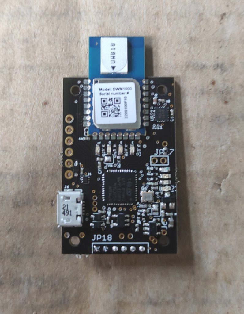
The tag is the device on every drone that enables the drone to locate itself within an enclosed space. The tag communicates directly with the anchors to determine its position via various protocols and calculations belonging to Tdoa3 . The tag is in turn equipped with a Dw1000 antenna and a serial connection that connects to the drone and also allows the tag to be powered.This device is also programmed with a proprietary firmware
Installation:
The system consists of variable numbers of anchors, each anchor is tested and pre-configured with its specific ID.For convenience, an identifier is applied on the back to recognize pre-configured ID.
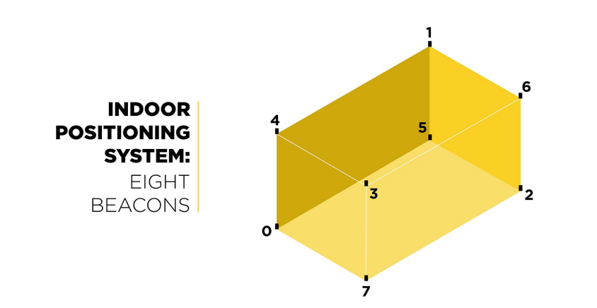
Our system is capable of working in both Tdoa2 mode and Tdoa3 mode . The Tdoa2 mode is limited by the number of anchors which can be up to 8 , while the Tdoa3 mode , in addition to having other advantages in quality and reliability , supports more than 8 anchors in its system (The following is an example of a basic installation of a system with 8 anchors)
Anchors positioning:
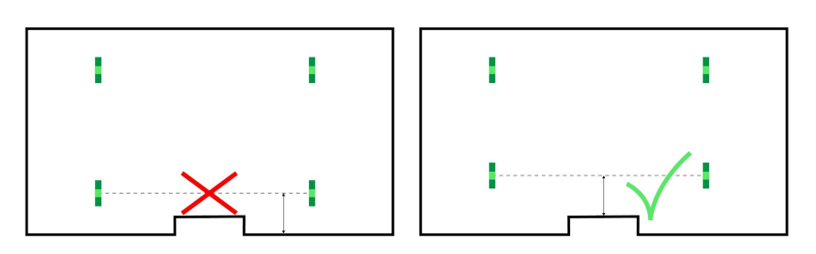
The anchors must be spaced from metallic (and concrete) objects including the support on which they
are fixed to avoid unwanted signal reflections. It is recommended to space the anchor antenna at
least 20 cm from any object or surface (walls, floor, ceiling), but greater distances even up to 80 cm
can improve performance. For the same reason, the space inside the volume defined by the anchors
must be as clear as possible (beams, columns, furniture, people, equipment …)
Also check that each anchor has line of sight with the other anchors and this has a minimum distance
of 20 cm from each encumbrance, greater distances even up to 80 cm can improve performance.
(plan view)
Arrange the anchors ( in this case 8 ) in the room as shown. The bottom anchors should be placed in a rectangular shape (minimum height from the ground 20cm, recommended 80cm) and the top 4 anchors should be placed in a rectangular shape (minimum distance from the ceiling 20cm, recommended 80cm).
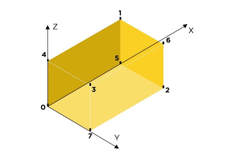
Establish a system origin (mark the X and Y axes on the floor). The reference system must be a left
handed coordinate system. You have to place the anchor 0 in the origin of the coordinate system (so it
will be close to one of the vertices of the flight area).
You will need to use this reference system to calculate the anchor positions, it can be useful to trace
the reference axes on the floor (note that walls, beams, tiles are usually not straight enough and with
right angles).
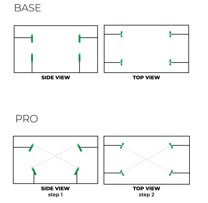
Anchors orientation:
In the basic configuration, all UWB antennas are positioned vertically like the tag on board the drone.
The ideal configuration is that the anchors point towards the center of the room and also inclined
towards the center.
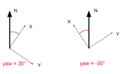
Reference system orientation :
The important data relating to georeferencing is the orientation of the system with
respect to the north, i.e. what is the orientation of the local X axis. To calculate it, you can position
yourself on the origin and observe the X axis with a compass (for example by reading the heading
reported by a drone). The BCN_ORIENT_YAW parameter must be set with that value.
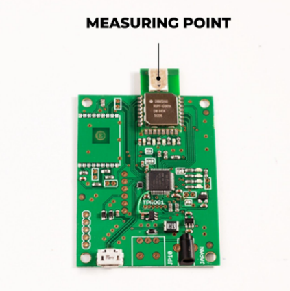
Measure the positions of the anchors :
After setting up the anchors in the space finally you can measure the X / Y / Z position of the
anchors in this coordinate system.
Measure as precisely as possible the positions (X, Y, Z) of the anchors. These are the centers of
the respective UWB antennas (see figure)
Settings the Anchor Position:
The coordinates of anchors 1 to n are relative to anchor 0 so if you have calculated the coordinates in
reference to a point on the floor you will need to subtract the position of the anchor zero from the
coordinates of the other anchors before proceeding with the setting.
| Anchor | Measured Positions | BCN_BCN*_(sub anchor 0) |
| 0 | 0.02,0,01,05 | none(0,0,0) |
| 1 | 5,0.1,0.55 | 4.98,0.09,0.05 |
| 2 | -0.3,7,0.45 | -0.32,6.99,-0.05 |
| … | … | … |
Anchor TX Power :
For much smaller setups (e.g. 4 x 4 x 4 meters) it is recommended to reduce the power.
While for larger setups it will be necessary to increase it. It is advisable to use the power necessary
for the size of your system, higher powers may be superfluous and increase system noise, worsening
accuracy.
| 4x4x4 | 21 db |
| 10x10x7 | 25 db |
| 15x10x8 | 27 db |
Parameters setting :
To set up the drone correctly, and make it able to communicate with the tag, it will be necessary to make sure that certain parameters are set correctly. However, the parameter list for the LuminousBee-Mini will soon be available and official on our website.
| Parameter Name | Value |
| SERIAL4_BAUD | 115 |
| SERIAL4_OPTIONS | 0 |
| SERIAL4_PROTOCOL | 13 *Only one Serial ! |
| BCN_TYPE | 64 |
| BCN_ORIENT_YAW* | For the calculation look further down |
| EK3_SRC1_POSXY | 6 |
| EK3_SRC1_POSZ | 1 |
| EK3_SRC1_YAW | 1 |
| EK3_SRC_OPTIONS | 1 |
| GPS_AHRS_USE | 0 |
